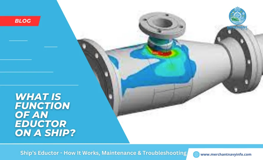
An educator is a simple type of pump that utilizes the “Venturi effect” to pump air, gas, or liquid from a specific area. Eductors can be used in any part of a ship, including hazardous areas, as they only require a propellant fluid or propellant to operate. When the propellant passes through the eductor in the required volume (which depends on the eductor design), a negative pressure is created within it. This negative pressure, or also vacuum, allows the educator to draw liquid or gas from a specific area. This liquid or gas is then pumped out through the propellant outlet.
What Are Educators Used For?
Eductors are used in many industries where a cost-effective alternative to centrifugal pumps is required. They handle granular or slurried solid waste, mix liquids, generate vacuum, agitate, and pump liquids. They are often used as main pumps in hazardous areas as they are inexpensive and have no moving parts. On ships, they are also used as suction pumps for centrifugal pumps, stripping pumps for ballast treatment, vacuum toilets, generating vacuum for freshwater systems, and pumping sludge and residues from oil tankers.
How Ship Educators Work
Educator work according to Bernoulli’s principle. It states that an increase in the velocity of a fluid occurs simultaneously with a decrease in pressure. For compressible flows, see the simplified Bernoulli equation below:
Where,
v = velocity of the liquid,
p = pressure of the liquid, and
ρ = density of the liquid.
From the equation, it is clear that as velocity increases, pressure decreases and also vice versa. In other words, it is an equation of conservation of energy. Now, look at the piping arrangement shown below. The volume of liquid (Q) flowing through a pipe is the product of the cross-sectional area of the pipe (A) and the velocity of the liquid (v). Or, Consider a constant flow of fluid in a pipe. The cross-sectional area of the pipe at point 1 is greater than the cross-sectional area at point 2.
Since the exit volume is the same throughout the pipe, the velocity of the fluid at point 2 increases compared to the velocity at point 1. In other words, the geometry of the pipe shown above causes the velocity of the fluid to increase at point 2. According to Bernoulli’s principle, as the velocity of a fluid increases, the pressure decreases. Hence, there is reduced pressure or vacuum at point 2.
How An Ejector Works In Ships?
The propulsion fluid (usually sea water or ship’s air) can flow through the nozzle (3) and diffuser (2), as shown in the diagram. When the motive fluid reaches the desired pressure and volume, it starts sucking from the suction side.
Normally, valves are connected to the motive fluid inlet, outlet, and also suction sides of the ejector. To operate the ejector, follow the steps below:
- Open the inlet and outlet valves of the suction pump.
- Start the suction pump (usually a fire pump) and adjust the pressure to reach the capacity required for it to operate. The suction pressure varies with the outlet height.
- Then, open the suction valve so the pump can draw from the desired compartment.
- Do not open the suction valve before the desired suction fluid volume has been reached.
- When stopping, close the suction valve and then stop the driving fluid. (This is for the same reason as above.)
The design parameters of a typical bilge ejector used on a ship are as follows:
- Propulsion fluid pressure: 7 kg/cm2
- Propulsion capacity: 20 m3/h
- Suction head: -7 mAq
- Suction capacity: 5 m3/h
- Discharge height: 6 meq
- Weight: 20 kg Ejector
Performance Curve
The suction flow rate curve shown below shows the suction capacity at the same discharge height. It changes with changes in driving fluid pressure. For example, if the head is maintained at six mAq, the suction will be three m3/h or five m3/h at driving pressures of 5 kg/cm2 or 7 kg/cm2, respectively. Increasing the driving fluid pressure above the design pressure does not increase the design suction capacity. Conversely, decreasing the driving pressure below the design pressure reduces the suction power. Again, a higher discharge head (or higher back pressure) reduces suction power.
Marine Ejector Maintenance and Troubleshooting
Nozzle or Throat Clogged
The most common cause of ejector problems is foreign objects restricting fluid flow in the nozzle or throat. Particles stuck in the nozzle or throat can be removed with a soft material such as wood. Do not use hard or sharp materials, as they may permanently damage the ejector.
Low Drive Pressure
If the drive fluid pressure falls below the specified value, it may result in loss of suction or fluid backflow to the suction side.
High Back Pressure
If the drive fluid back pressure increases, the suction force will decrease significantly. This effect can be reduced by increasing the drive fluid volume or pressure. Therefore, back pressure must be monitored at all times during the ejector’s operation.
Design Features and Assembly
Ejectors consist of a cast/alloy/stainless steel body, a driven fluid nozzle assembly, a converging inlet nozzle, screws, sealing O-rings, a suction pipe, a suction chamber, a diffuser, and an outlet.
Pumps are designed with a conical-shaped jet or nozzle within the suction chamber. This jet or nozzle is positioned so that the liquid exits axially outwards towards the outlet or diffuser outlet.
Directly below this nozzle is the suction tube, which is used to suck in any type of liquid that needs to be extracted or pumped out of the system.
However, the flow side is connected to the driving fluid. With the continuous flow of driving fluid and the Venturi effect, the pump sucks in water and expels it from the outlet through the diffuser, improving the pump performance.
Applications of Ejectors in Ships
- For vacuum generation in freshwater generating units
- As a vacuum toilet system
- As a self-priming system in centrifugal pumps
- Foam applicator in fire fighting system
- For pumping water from boatswain’s camps, chain boxes, etc.
- As a scraper system in Frammo ballast pumps


