Loadline Marks were among the first safety features introduced in the shipping industry. When they were introduced, ships suffered heavy losses due to overloading. Lord Plimsoll, a Member of Parliament, fought for the introduction of loadline marks, hence the term “Plimsoll Disc.” The safety of the ship is paramount, and you must put all your energy into this direction. An overloaded ship is unsafe as it does not have enough reserve buoyancy and strength to withstand bad weather.
How, When, and Why LoadLine Marks Came?
The origins of loadline mark can be traced back to 1876 when a British Member of Parliament named Samuel Plimsoll actively advocated for the Merchant Shipping Act 1876 (MSA). This law was the first legislation requiring all ships to carry loadline mark on both sides of the ship.
The idea was to provide safety on board for sailors against the greedy shipowners of the time who were only interested in maximizing profits by constantly overloading their ships, thus endangering safety and lives at sea.
The 1966 Load Line Rules under this Convention are now in force and deal with all details relating to ship strength, subdivision, watertight closing arrangements, weathertight closing arrangements where required load line markings, and allocation of limits of freedom.
The ship’s load line certificate is displayed on board, and the master records the navigational draught and limits of freedom in the official log book. If the ship fails to comply with the limits of freedom requirements and LL regulations, severe penalties and detention may be incurred.
Criteria for designating loadline marks
Load lines are set to ensure that the ship has sufficient limits of freedom to navigate the sea under the prevailing weather conditions.
In such appointments, the following conditions are considered:
Sufficient limits of freedom to provide reserve buoyancy even when the ship rolls and pitches.
Hull strength (for ships designed to be submerged to the design draught)
Ability to drain seawater from the roof. Ships are equipped with decks or bulkheads with handrails only, and scuppers are provided in the bulkheads. Ships also have sloping decks where the decks are raised fore and aft to allow drainage. The ship also has a bow to allow water to drain into a gutter.
A method of closing multiple openings on the main surface.
The subdivision of the structure ensures damage stability even in the event of flooding of one or more compartments.
Surface line location, Plimsol disc, and custom free frame.
The deck line is located where the upper continuous plate (weather deck) meets the bow plate (the upper plate (plate) at the side of the ship) in the middle of the ship.
If you are on a ship with a rounded bottom plate, you will notice that the deck line is located at the bottom where the curvature of the deck plate ends.
Marking, size and location of various load line marks

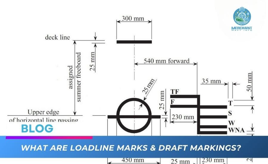
As shown in the figure, a set of lines runs along both sides of the ship and along both sides of the middle of the ship. These lines are called load lines.
The roofline is on top. It is 300 mm long and 25 mm wide, and its upper edge is on the continuous waterproof upper deck line.
A vertical circle with an outer diameter of 300 mm is below the roof line. It is called the load line disc or Plimsoll.
A horizontal line 450 mm long and 25 mm wide cuts through the load line disc. This line is called the Plimsol. Its upper edge passes through the center of the disc. The letters L and R are the initials of the notified body (in this case, Lloyd’s Register). These letters may sometimes be the initials of IR AB, BV, or any other notified body. IR stands for Indian Register of Shipping. The letters are 115 mm high and 75 mm wide. The gap between the Plimsol font and these letters is 38 mm high.
A set of lines, each 230 mm long and 25 mm wide, marked TF, F, T, S, N, and WNA, are located 540 mm in front of the center of the load line dial. They are located on the right side of the right dial and the left side of the left dial (i.e., in front of the Plimsoll marking).
Load Line Zones
The ocean is divided into different zones, including:
- Summer – S
- Tropical – T
- Winter – W
- Winter North Atlantic – WNA
- Freshwater – F
- Tropical Freshwater – TF
Loadline Marks
In the above image, you will notice two sets of frog lines. The right set is the normal loading line, which includes markings for ships with timber or logs on deck. (hence the prefix “L”)

Load Lines and Zones
A zone is defined as an area to which a date is applied on a special load line zone chart. This chart is prominently displayed on the bridge and in the shipping office. A particular zone can be a summer zone during some months and a tropical or winter zone during the rest of the months (see the zone chart on board). These are called seasonal zones.
The ship must always ensure that the corresponding load line is not submerged in port at any voyage stage or when passing from one zone to another.
When the ship is in the equatorial zone and 1025-density water, its load must not exceed the upper edge of the line marked T.
When the ship is in the summer zone and 1025-density water, its load must not exceed the upper edge of the line marked S. Incidentally, this line is at the same level as the line through the center of the disk loading line.
When the ship is in the winter zone and 1025-density water, its load must not exceed the upper edge of the line marked W.
During the winter in the North Atlantic, the sea is rough, and if small ships are allowed to load, even as far as the southwest, it may not be safe. The upper edge of the WNA line, 50 mm below the W line, is the maximum that can be loaded in 1025-density water. This restriction does not exist for ships over 100 meters in length.
When the water density is 1000, i.e. in fresh water and summer areas, the ship can be loaded to the upper edge of the line marked “F”.
When the density is 1000, i.e. in fresh water and tropical areas, the ship can be loaded to the upper edge of the line marked “TF”.
Spacing between seasonal load line marks
The distance between the center of the disk and the deck line is determined by the designated body and depends on various factors, including ship size, hull, waterproofing measures, type of cargo transported, etc. The draft on the S line is the summer cargo draft.
The distance between W and S, between T and S, and between TF is the same and is equal to 1/48 of the summer cargo draft.
The distance between S and F is equal to the distance between T and TF and is the ship’s fresh water allowance (FWA).

Commodity marking designator
The ship’s flag state is the authoritative body. In many cases, it delegated the inspection and allocation to the classification society, which assigned the mark to the ship and issued the certificate on behalf of the flag state.
Reading the loadline marks:
The rings, lines, and letters will be drawn in white or yellow on a dark background or in black on a light background.
Both sides of the label must be permanently marked.
The mark must be visible. All readings are taken from the top of the corresponding loading fork mark.
Understanding and using draft labels
There are six places where draft marks are found on the ship.
On both sides of the arc
On both sides of the middle of the ship
On both sides of the buttocks
Draft marks can be in meters, feet, or both, that is, in meters and feet.
What are the Four Cardinal Marks?
Draft marks
Drag marks are numbers painted on the bow, midships, and stern of the ship. They indicate the depth of the ship’s keel below the waterline.
The numbers on the counter are 10 cm high. Between the meter marks, slightly to the right, are marked the Arabic numerals 2, 4, 6, and 8, which represent 20 cm, 40 cm, 60 cm, and 80 cm, respectively. The distance between these Arabic numerals is 10 cm. The bottom of the numerals indicates the draft.
If the water level touches the bottom of “10”, the draft will be 10 meters; if the water level touches the bottom of 2, the draft will be 10 meters 20 cm; if the water level reaches the peak of 2, the water depth will be 10 meters 30 cm. The draft must be estimated if the water level is at any level other than the upper or lower limit. The thickness of all markings is 1 cm.
The feet are marked with Arabic numerals or Roman numerals. In both cases, the markings are 6 inches high. If the water level reaches the bottom of 12, the water flow will be 12 feet. If the water level touches the top at 12 feet, the water flow will be 12 feet 6 inches. If the water level is halfway between the top 12 and the bottom 13, the draft will be 12 feet 9 inches; the thickness of the markings is 1 inch.


