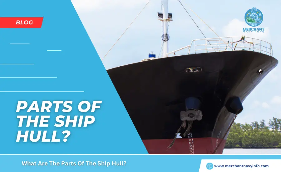
The hull of a ship is the main buoyant body of any ship, and displacing water contributes to the buoyancy. That keeps the ship afloat, as defined by Archimedes’ principle. From a static point of view, a ship’s hull has its outer shell waterproof or intact. And the upper part is closed off by the main deck or weather deck. This deck is actually also known as the Starch Deck or Exposed Deck. The structural unit above this main deck level is called the superstructure or deckhouse. Now, let’s move on to the main body. Its different parts can be defined from different perspectives.
Structure
As you know, the main longitudinal and transverse strengths. Of a ship can be defined by the strength of the hull of a ship beams. Technically speaking, this means that all kinds of loads act directly on the torso. Therefore, structural design is a decisive factor in assessing the load-bearing capacity of a ship structure. The deckhouse, or superstructure, contributes to the structural strength of the ship, but primarily at the local level. In other words, local effects on the structure caused by direct loads. And vibration effects are most prevalent in the superstructure and deckhouse. However, from a total load perspective, most of the effects are based on a response of the hull of a ship structure itself.
Two Major Components
For example, we will discuss her two major components of the longitudinal response of a ship due to overall loading:
- Deflection
- Distortion.
From the point of view of the behavior of the hull of a ship structure as a simply supported beam. In other words, the effect of longitudinal loads on the ship. Can be defined by considering the ship as a beam. In this case, hydrodynamic and hydrostatic loads act as forces. And the entire hull of a ship structure behaves like a bending beam. Similarly, when a lateral load is applied perpendicular to the ship’s center line, the hull in ship structure behaves appropriately depending on the size and type of the approaching load.
To absorb these lateral and longitudinal loads acting on the entire hull in ship structure, there are, as you know, a large number of reinforcing elements associated with different types of external and internal plating. As you know, in long ships with a large length-to-beam ratio, longitudinal loads have a greater effect than transverse loads. Similarly, a short vessel with a low length-to-width ratio will have a greater impact on lateral loads than on longitudinal loads. Furthermore, from a purely structural point of view, the various units of the ship’s hull can be classified as follows:
Hull Skin
This is the external structure of the main hull in ship and consists of welded plates of varying thickness and size. On most ships, the outer shell coating material is made of various grades of steel, while on some ships, composite materials such as FRP and aluminum are used. Before steel was used on a large scale, iron was widely used, and early in history, wood was used. The hull skin can be further subdivided into:
Lower Shell Structure
These are the panels in the lower area of the hull. The exact definition of bottom armor varies depending on the ship’s design, but it is typically used for flat or sloped plates that start at the ship’s baseline and continue on both sides. The board that coincides with the center line of the ship is called the keel. From a practical point of view, this is the panel with the highest proportion of square timber on the entire ship. This means that this plate is the thickest.
There are Many Reasons for This
The bottom of the ship is the area exposed to the highest structural loads and also absorbs all connection loads from the rest of the ship. All loads are also greatest near the centerline of the ship. Moreover, this particular region also experiences the greatest degree of displacement or deformation tendency under the influence of various loads during deflection and buckling. In many ships, the upper part of the bottom shell structure is curved, and this curved plate is also called the bilge plate or bilge turn. The plates placed directly on either side of the keel are called garboard strakes and are also quite thick.
Side Shell Structure
Placing panels from bottom to top directly next to the bottom structure is called side shell plating. These plates are arranged vertically and define the lateral dimensions of each ship. The top plate of the side shell directly adjacent to the upper deck is called the shear strip. These panels are exposed to high shear stresses and, therefore, have a high slope.
Deck Structure
A deck is simply a horizontal, continuous surface with important dimensions in the construction of a ship. The word important is important. This is because, for practical reasons, the deck needs to be at least a few frames long and preferably also some minimum width on the left and right sides. Depending on requirements, smaller decks may also be available. These small, irregularly spaced decks are sometimes called platform decks, but they do not contribute much to the overall strength of the ship. Now, as you know, the main deck forms the upper limit of the main hull.
From a practical point of view, it is often fully or partially exposed to external weather conditions and is referred to as clapboard or exposed decking. It also contributes significantly to the longitudinal strength of the hull beam and is, therefore, called the strength deck. There may be other decks within the main hull or superstructure, and larger ships have their own numbering system for decks based on their height from the bottom. Common code names for superstructures or deckhouses include bridge deck, bridge deck top, and wheelhouse top.
Bulkheads and Boundaries
As you know, a bulkhead is a boundary or division that separates two departments or spaces. They are either vertical or horizontal in nature. These are important elements contributing to the strength of the ship as they connect between her two decks. They are located in both the main fuselage and the superstructure. Boundaries are similar to bulkheads and are often used for tanks and compartments of different sizes.
Strengthening of Members
As we all know, ships now have to be structurally reinforced in all respects in order to withstand all kinds of loads from a local and global perspective. Reinforcement members can be classified as follows: Main component
This member is the main member who contributes to our strength. Although classified separately, structural panels (shells), decks, and bulkheads (over a certain length or span) are major elements in their own right. Otherwise, the various types of primary structural members are essentially civil engineering structural members such as deck beams, lower shell beams, side frames, vertical beams, etc. These are directly responsible for supporting most of the overall loads acting on the ship’s structure.
Auxiliary Components
These essentially include reinforcing components. These can be transverse, longitudinal, or vertical reinforcements or other supports such as columns or supports These basically absorb the loads transferred from the main beam and, at the same time, support the main beam. For example, longitudinal reinforcement serves to absorb loads from deck slabs and beams and provide longitudinal strength. Similarly, the vertical stiffeners that support the partition serve to support the loads from the partition frame and panels. These secondary elements have smaller dimensions than deep elements and are more common at certain distances. These can be continuous in nature or interrupted by other members.
Tertiary Elements
These include elements such as brackets, slabs, rods, and insert plates. These reinforce members who are connected to secondary members and often provide support and connection to the secondary members. For example, brackets can provide support and also define a load path for power transmission through connections between vertical reinforcement on the deck and vertical reinforcement on the bulkhead.
Often used for selective reinforcement in certain locations with secondary links. For example, at deck openings, additional flat bars can be used with small reinforcements to provide localised reinforcement to compensate for the loss of strength near that area. Other elements include A-brackets, couplings in the engine or mechanical room areas, corrugated stairs, perforated plates, chequered plates, etc. Based on location, We are all more or less familiar with this classification.


