Oil tankers transport oil of various grades and qualities and, therefore, tend to generate flammable vapors and gasses when loaded for transport. Even when there is no cargo on board, harmful flammable gasses may be present in the cargo holds. When vapors emanating from oil cargoes mix with a certain concentration of air, mainly containing oxygen, they may cause an explosion, resulting in property damage, marine pollution, and loss of life. On board ships, inert gas systems are used to prevent such explosions. This may be a separate inert gas system on a ship or it may also be flue gasses produced by the ship’s boilers.
What Is Inert Gas, Inert Gas System?
Inert gas systems on ships are the most important integrated systems for oil tankers for the safe operation of the ship. It is a gas that does not contain enough oxygen (usually less than 8%) to suppress the combustion of flammable hydrocarbon gases. The inert gas system on the ship distributes inert gas into the oil-hydrocarbon mixture, thereby raising the lower explosion limit (LEL) (, the lower concentration at which the vapors can ignite) and, at the same time, lowering the upper explosion limit (HEL) (the higher concentration at which the vapors can explode). When the concentration reaches about 10%, an atmosphere is created in the tank where the hydrocarbon vapors cannot burn. The inert gas concentration is kept at about 5% as a safety limit.
I.G. System Components and Description:
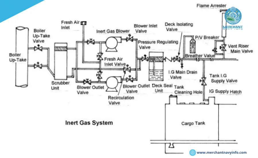
In a typical inert gas system on the ship on an oil tanker, the following components are used:
1. Exhaust Gas Source:
The inert gas source is taken from the boiler or also main exhaust intake as the engine contains exhaust gases.
2. Inert Gas Isolation Valve:
It acts as the supply valve from the suction to the rest of the system and isolates both systems when not in use.
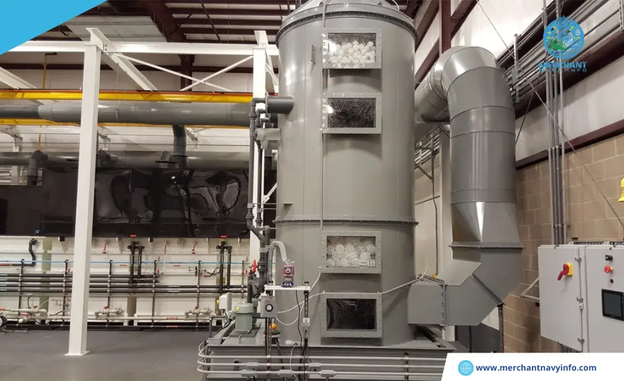
3. Scrubbing Tower:
Flue gas enters the scrubbing tower from below and passes through a series of water sprays and also baffles to cool, purify and also humidify the gas. The SO2 content is reduced by up to 90% and the gas becomes soot-free.
4. Demister:
Usually made of polypropylene, it is used to absorb moisture and also water from the treated flue gas.
5. Gas Blower:
Two types of blowers are generally used – steam driven turbine blower for the I.G. operation and electric blower for refilling.
6. I.G. Pressure Control Valve:
The pressure in the tank varies with the oil properties and also atmospheric conditions. To control these variations and to avoid overheating of the blower, a pressure control valve is fitted after the blower discharge which returns the excess gas back to the scrubber.
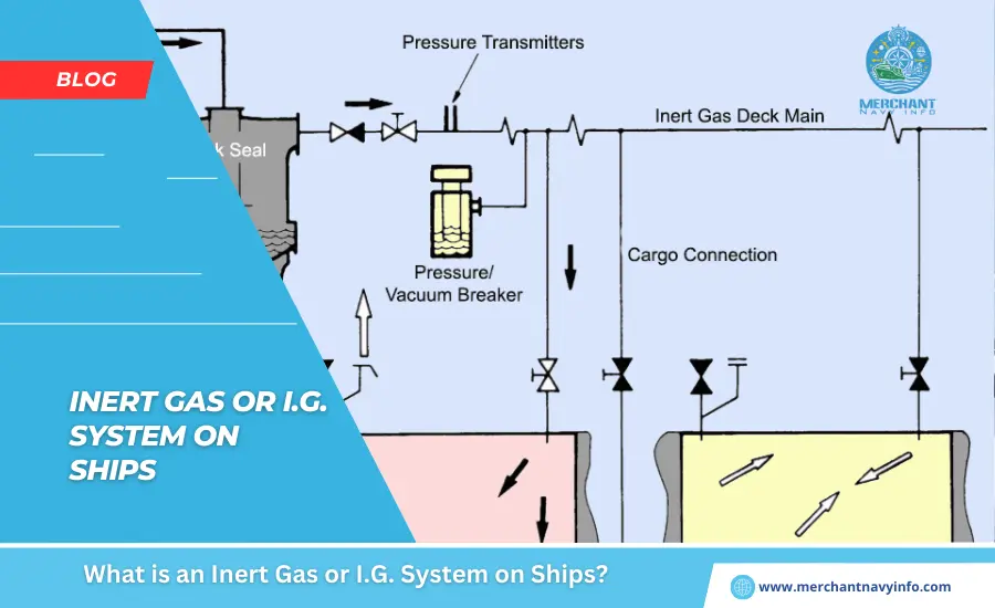
7. Deck Seal:
The purpose of a deck seal is to prevent the gas from the blower from flowing back into the cargo tanks. Usually a wet deck seal is used. A demister is installed to absorb the moisture contained in the gas.
8. Mechanical Check Valve:
This is an additional mechanical check valve associated with the deck seal.
9. Deck Isolation Valve:
This valve can be used to completely isolate the engine room system from the deck system.
10. Pressure Vacuum Breaker (Pv):
P.V. breaker helps in controlling over pressure or negative pressure in the cargo tanks. The P.V. breaker vent is equipped with a flame trap to prevent the outbreak of fire during charging or discharging process at port.
11. Shut-Off Valve For Cargo Tank:
A ship has several holds, and also each hold is equipped with a shut-off valve. The valve controls flow of inert gas into the holds and is operated only by responsible personnel on board.
12. Mast Riser:
Mast riser is used to maintain any positive pressure of inert gas when loading cargo and is kept open during loading to avoid pressure build-up in the cargo tanks.
13. Security And Alarm Systems:
The inert gas system on ship is equipped with various safety features to protect the tanks and also their machinery.
Following are the various alarms (with shutdown) built into the inert gas system on ship on board:
- High levels in the scrubber will cause an alarm and shut down of the fan and also scrubber tower.
- Low pressure seawater supply (approximately 0.7 bar) to the scrubber tower will lead to an alarm and fan shutdown.
- Low-pressure seawater supply (approximately 1.5 bar) to the deck seal will lead to an alarm and fan shutdown. 70 °C) will cause an alarm and also shut down the blower.
- A drop in pressure in the lines after the blower (approximately 250 mm water column) will cause an alarm and shut down the blower.
- A high oxygen content (8%) will cause the blower to shut down. An alarm will cause the gas supply to the deck to shut down.
- A drop in the deck seal level will cause an alarm and shut down the gas supply to the deck.
- A power failure will cause an alarm and shut down the blower and scrubber tower.
- An emergency stop will cause an alarm and shut down the gas supply.
Blower and Scrubber Tower Shutdown
The various alarms integrated into the inert gas system on ship are listed below:
- Scrubber level low
- Deck seal high-level
- O2 content low (1%)
- O2 content high (5%)
- Low lubricating oil pressure alarm How the inert gas system on ship works.
The Basis For Inert Gas Production
In I.G. plants, flue gases are produced by the ship’s boilers. The hot gas mixture from the boiler suction is processed in the inert gas system on ship , which cleans, cools, and also supplies the inert gas to the individual tanks via P.V. valves and breakers, ensuring the safety of the tank structure and atmosphere.
Systems Can Be Divided Into Two Basic Groups:
- Production equipment that generates the inert gas and supplies the gas under pressure to the cargo tanks using blowers.
- Distribution systems that control the passage of the inert gas to the appropriate cargo tanks at the required times.
Short-Time Operation Procedures
- The boiler suction gas is sent to the scrubber unit through the flue gas shut-off valve.
- In the scrubber unit, the gas is cooled, cleaned, and also dried before being fed to the tank.
- A motor-driven inert gas blower sends the treated gas from the scrubber tower to the tank. These are mounted on rubber vibration dampers and also isolated from the pipeline by rubber bellows.
- Regulation of the amount of gas supplied to the deck is performed by a gas control valve while the deck pressure is controlled by a pressure regulator. If the deck pressure is lower than the set value, the output signal increases and also the valve opens further, and also vice versa if the deck pressure is lower than the set value.
- These valves work together to maintain both deck and also blower pressure at their respective set values without interrupting or also overloading the circuit.