What is a steering gear, and what is it used for?
A steering gear is a machine on a ship that controls the ship’s movement from the left (port) to the right (starboard) when the ship is moving. When the ship is stationary, the steering gear has no effect.
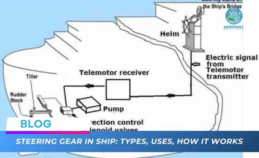
The steering gear provides rudder movement in response to signals from the bridge through a control device. The device transmits the required rudder signal from the bridge and activates the steering gear to move the rudder to the desired angle.
This system can be of different types (hydraulic, electro-hydraulic, electric), but mostly on ships, you will find the electro-hydraulic type. The most common types of ship steering gear are the 2-piston, 4-cylinder Rapson sliding vane, and electro-hydraulic rotary vane.
Rotary vane steering gear
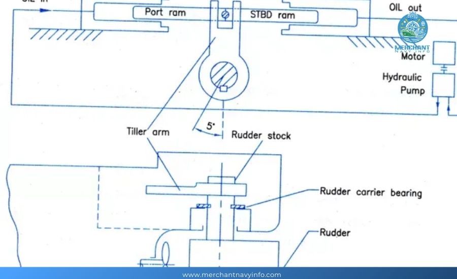
In the first case, the steering gear consists of two pistons and four hydraulic cylinders operated by two electric pumps, one of which is a backup pump. These pumps have variable displacement axial pistons and separate hydraulic oil tanks. Each main pump is directly connected to an auxiliary gear-type pump, which supplies oil to the servo system, drives the oil, and cools the pump housing.
Both pumps can put the rudder to the working angle at a given time. In normal operation at sea, one pump is sufficient, but a second pump set can be connected anytime by starting the engine. Both pumps must be in operation when maneuvering or operating in calm waters.
In the second case, the steering gear system consists of an electric motor, a power unit, an electrical/hydraulic control system, and related electrical components. The engine has a vane rotor, and the hydraulic pressure is transmitted to the rudder/rudder shaft by a friction connection between the rotor and rudder shaft axes. There are two sets of compression chambers and return chambers in the engine/rotor housing. The internal oil is distributed by using channels in the cover, which guide the oil to the compression chambers and away from the return chambers.
Immersion Suit – Different Types, Anti-Exposure Suits, And Thermal Protective Aids
What are 5 Interesting Facts About Panama?
Understanding 10 Types of Decks
World of Marine VHF Radios, GPS, and Autopilots
The control valve opens and closes the oil flow channel; four cross-connected valve blocks are installed on the cover. All valves are open in normal full operation, but two are closed if the steering column is divided into two units. The dividing wall of the oil pressure chamber acts as a mechanical barrier for rotor movement and rudder angle limitation.
The rotor has upper and lower radial bronze bearings and a vertical bronze rudder bearing lubricated by hydraulic oil from the pressure chamber. The rotor has two blades, and the casing is divided into two cylinders with two mechanical seals mounted in the casing.
Spring-loaded cast iron sealing rods seal the pressure chambers, and gland seals connect the engine and rudder. On top of the engine is a header/expansion tank that serves as a reservoir for the system oil. The system includes two motor and pump units: a motor, a hydraulic pump, an oil tank, and a filter. Electric solenoid and hydraulic slide valves mounted directly on the engine casing control the rudder.
An automatic isolation system is integrated into the four-ram steering gear. The hydraulic systems are connected via a solenoid-operated isolation valve, which enables the two systems to work together to produce the torque required to move the rudder in normal conditions. When one system fails, and hydraulic oil is lost, the float switch in the affected hydraulic oil tank is activated. It sends a signal to the isolation system, which divides the steering gear into two independent systems.
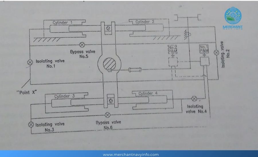
The faulty system is isolated, and the pump is shut down while the healthy system continues to operate normally and maintains steering power. However, only half the rudder torque is available. When a fault in the hydraulic oil line causes the “low” level switch to operate, the isolation valve operates, dividing the hydraulic oil circuit into system 1 and system 2, thereby reducing the steering power by 50%.
Therefore, when a “low” level alarm is issued, the ship’s speed is immediately reduced, or the steering angle is limited to 15 degrees if the ship continues moving forward. It should be noted that the “low” tank level switch for visual and audible alarms is set per classification society rules and regulations, and the automatic isolation switches of the systems are installed separately and independently of each other. However, when the same oil level is reached, both will open.
Hydraulic oil tank on four-piston steering gear
The guide gear design also meets the requirements for double separation during operation for rotary blade guide gears. It is possible to disconnect (adjust to bypass) one rotor blade and operate the steering gear with the other blade. It is also possible to disconnect (adjust to bypass) one stopper and operate the steering gear with the other stopper.
These separation devices provide efficient single-cylinder operation, with pressurized oil supplied on one side of the blade or plug and oil discharged on the other side. Individual blade separation is a fully automatic function activated by a fault in the oil distribution system, but it is also possible to disconnect the blade manually from the control on the bridge.
The steering gear can be operated as a single or two actuators operating on different sides of the same plug. To achieve these forms of separation, the cab panel has MAN SEP1 and MAN SEP2 buttons.
There is a test/function switch on the main panel in the steering equipment room that allows all different arrangements to be tested. Each pump can be operated with separate blades and seals. The switch should normally be in the normal operating position. Other switch positions are also available, but they are only used for testing and simulating separation conditions and should not be used for normal operation of the steering equipment.
The autopilot control or manual steering from the cab is used to control the steering equipment. All commands are transmitted to the cab electrically, and the actual position signal is provided to the system through the feedback transmitter of the steering equipment.
Limit switches limit the angle of the operating rudder movement to 35 degrees to the left and 35 degrees to the right. Still, mechanical stops are also installed to limit any movement greater than 37.5 degrees to the left or right.
Example of steering gear board on the bridge
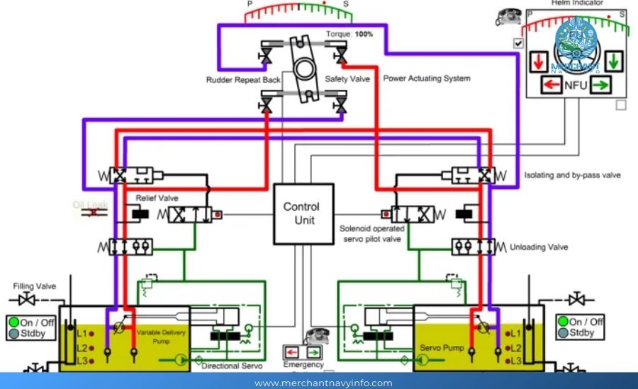
The variable flow pump is controlled by an electric torque motor connected to a servo valve through a control rod, which activates the servo piston that drives (pulses) the tilt rod. This moves the piston out of the neutral position and causes oil to be discharged to one pair of hydraulic cylinders while suction is drawn from the other pair of hydraulic cylinders.
The feedback linkage causes the pump tilt rod to move as the rudder rotates, reducing the stroke. When the rudder reaches the desired angle, the tilt rod returns to the neutral position, and the pump stops supplying oil.
In the case of the rotary vane type, the electrical signal activates the solenoid valve to direct the pressure and oil to or from the hydraulic cylinder formed by the vane, housing, and seal. The steering gear feedback transmitter provides the system with an actual position signal, keeping the bridge operator informed of the rudder’s actual position. Two blades are normally used, fed by either or both pumping units.
When maneuvering in calm waters, both pumping units are operated to achieve the IMO-required rudder angle movement of 35 degrees to one side and 30 degrees to the other in 28 seconds (56 seconds for one pump), but normally, the system performs these movements in a shorter time, e.g., 24 or 48 seconds, respectively.
In addition to the central steering control unit, the bridge control panel is equipped with a tiller FU (follow) and a tiller NFU (non-follow). The bridge wing is equipped with a tiller FU and a tiller NFU, allowing steering control from the bridge wing. The tiller FU allows normal (follow) steering from the control unit in the bridge or bridge wing. The tiller NFU is an emergency control unit, allowing emergency (or non-follow) control of the steering equipment.
The emergency procedure used depends on the nature of the fault. If the steering gear or the transmission system fails on the bridge, but the steering gear still works, steering can be done with the Tiller NFU in the bridge or bridge wing panel. Another option is to use the Tiller NFU in the steering gear room.
If the steering control system fails and the Tiller NFU fails, the hydraulic system must be operated manually, which involves local control of the pump’s directional steering valves. Solenoid valves or buttons at both ends of the control lever must be pressed to control the oil pumps, one to the left and one to the right to turn the rudder.
Example of a red-lever steering gear pump for emergency steering
Instructions must be sent by telephone from the bridge to the router room. Since the pump directional pilot valves are manually controlled individually, it is impossible to ensure full simultaneous control of both pumps. Only one pump unit can be operated when emergency control is taken from the steering gear room.
The company’s instructions for operating and inspecting the router under all conditions are displayed on the router’s local control panel and must be followed at all times. These periodic checks are:
Daily checks:
Check the oil level in the pump reservoir and refill as necessary. The level should not exceed 3/4 of the glass at normal operating temperature.
- Check system pipes and valves for leaks.
- Check the lubrication system and refill the priming pump reservoir as necessary.
- Monitor the oil temperature in the hydraulic system.
- Visually inspect components such as indicators and tie rods.
- Check the readings of measuring devices for abnormalities.
- Check for abnormal sounds when the rudder is moving.
Ensure that the rudder bearing lubrication system is working properly and that the container has enough grease.
Monthly checks:
Check the tightness of all connecting bolts and pipe connections.
- Check the limit switch settings.
- Perform a functional test on the alarm system (refer to the manufacturer’s operating manual for full details).
- Ensure that the rudder indicator is working properly.
- Check the filling device oil seals and pump controls.
- Check the stop and isolation valves.
Although the steering mechanism can be opened and closed on the bridge, a service engineer must be present at these times and when the pre-departure tests are carried out. The service engineer can detect faults that are not serious enough to trigger the alarm.
At sea, when a single pump operates the steering gear, the operating pump must be changed every day so that the operating time of the three pumps is equal.