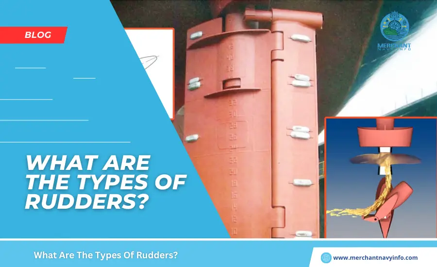
Have you ever noticed that, unlike most aeroplanes, ships don’t have the same rudder? The type of rudder ship that is suitable for a particular ship depends on the hull shape, speed, propeller design, stern structural arrangement, and propeller. The decision should be based on various factors, such as the distance between the stern and stern and hydrodynamic factors that affect water flow. Decide on the propeller at the back.
The way ship designers decide on the rudder ship type is actually an iterative process. At the ship concept design stage, you don’t actually decide (or can’t afford to) on the right rudder for your ship. So, designers and naval architects estimate the very rough dimensions of the rudder ship and the propeller. However, once you begin the preliminary design of your ship, the dimensions of the rudder ship and propeller are approximately determined, so it is more or less clear which type of rudder ship will best suit your design problem. However, from a designer’s point of view, it is important to determine the type and location of the rudder depending on the hull and propeller design.
Let’s Understand this Briefly
Selecting the correct type of rudder is as important as the position of the rudder behind the propeller. The position of the rudder must be properly aligned in the direction of the outflow of the propeller in order to produce the required torque for the ship. Small changes in rudder type, rudder dimensions, and rudder position can significantly change the ship’s response to the rudder and the ship’s ability to turn. Therefore, optimization is important.
Types Of Rudder
Oars Broadly classifying traditional oars, there are two types of marine oars:
Spade or Balance Oar
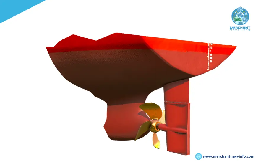
A spade oar is basically a rudder plate that is attached only to the top of the rudder stock. Oar’s. In other words, the rudder axle (or rudder axle) does not extend downward along the rudder span. In practice, the position of the rudder stock along the rudder chord (meaning the width from the front to the rear of the rudder) determines whether the rudder is a balanced rudder or a semi-balanced rudder. A balanced (spade oars are common), the rudder stock is located such that 40% of the rudder area is in front of the stock, and the rest is behind the stock.
The real question that must be on your mind is why such a position was chosen for the helm. The answer lies in simple physics. The center of gravity of the rudder is approximately 40% of the chord length from the leading edge. If the rudder shaft is located near this position, the torque required to turn the rudder is much less than the torque required to move the rudder if the shaft is located at the forward end of the rudder. This reduces the energy required by the steering system and reduces the vessel’s fuel consumption.
Unbalanced Rudders
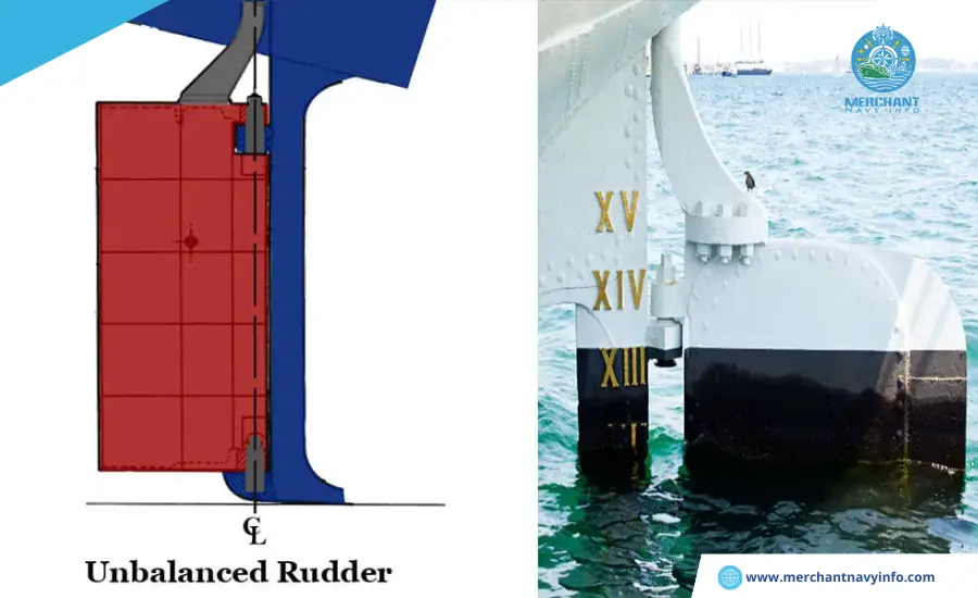
In these oars, the shaft is attached to the most forward point of the span. Unlike a balanced oar, the rudder stock runs along the chord length of the oar. The reason is simple. In this case, the torque required to turn the rudder is much greater than that required for a properly balanced rudder. Therefore, the top of the rudder must be attached to the main shaft to prevent vertical displacement from its natural position. However, unbalanced rudders are not currently widespread.
Now that we’ve covered the traditional rudder, let’s move on to something more interesting. Researchers and ship operators have identified significant problems with balanced and unbalanced rudders. That is when the rudder mechanism malfunctions when turning the ship. In this state, the rudder maintains the angle of attack. A solution to this problem was found by developing an optimized semi-balanced rudder.
Semi-Balanced Rudder
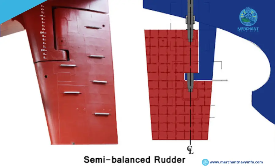
If you can imagine a balanced rudder and an unbalanced rudder, you should be able to easily imagine a semi-balanced rudder. In fact, the rudders found on most ships of modern industry are semi-balanced. The name “semi-balanced” itself means that the rudder is partially balanced and partially unbalanced. If you look at the image below, you can see that some of the string lengths are unbalanced when viewed from above, while the remaining string lengths are balanced. Why Keep reading?
The unbalanced upper part helps provide structural support for the rudder during vertical displacement. And the more balanced part produces less torque when turning the helm. This allows the semi-balanced rudder to automatically return to the centerline position if the rudder equipment fails during a turn.
Notice the control horn in the image above. There are two types of semi-balanced rudders, depending on horn depth (which affects the rudder’s response and torque characteristics). A flat-horn rudder has a horn that extends from the tip for just over half the chord length of the rudder.
On the other hand, in a deep horn rudder, the horn extends over 50% of its chord length from the tip of the rudder. That said, designers have developed other unconventional rudder systems that are more interesting to consider.
Flap Rudder
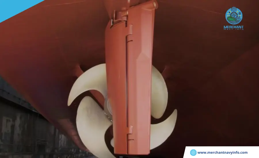
You must have looked carefully at the wings of an airplane. Have you ever seen the rear wing flaps expand and retract? Why do you think they do this? It primarily changes the effective angle of attack of the entire wing section. During startup, you will see all flaps fully extended. This actually helps achieve an effective angle of attack for maximum lift.
The same principle can be used to achieve similar results in rowing. However, on the rudder the flaps are not retractable and have a significant effect when the rudder is given a certain angle of attack.
Pleuger Ruder
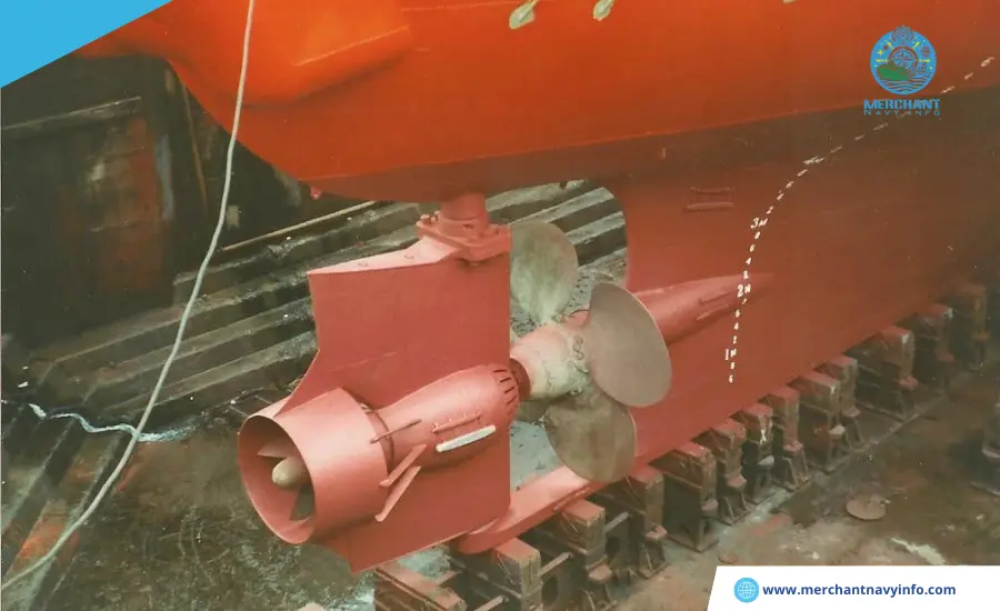
Probably one of the most innovative rudder mechanisms I’ve ever come across. Suppose you have a ship that is too large to maneuver within a basin with size restrictions, and you cannot use the propeller while maneuvering. This situation often occurs on large ships navigating in basins with limited space and during slow navigation.
Thus, Pleuger Rudders (as you can see in the image below) houses a small auxiliary propeller (driven by a motor). This housing is attached to the rudder itself, which generates a thrust (smaller than that generated by the ship’s main engine propeller) in the direction along the rudder, allowing effective steering at low speeds.
Such rudders can also be used in normal conditions, although at normal speeds, the plunger will not work. However, when operating the plunger, the main engine propeller must not be operated at the same time. Otherwise, the plunger will be destroyed.
Voith Drive
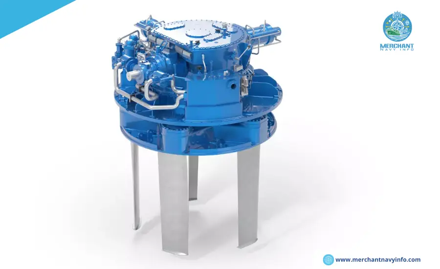
You may be wondering why the drive system comes up in the discussion if you are interested in the rudder system. Well, we have researchers to thank for that. This is because this propulsion system is unique and acts as a rudder itself. You don’t need a rudder oar to change the ship’s direction. how? Keep reading.
As you can see in the image below, this propeller has a completely different orientation. Simply put, it consists of a series of airfoil-shaped blades attached to a disc, which in turn is attached to the fuselage. The disc rotates about a horizontal axis in a horizontal plane, imparting rotation to the blade.
But How Does Rotation in the Horizontal Plane Give the Ship Thrust?
This is the answer. The blades themselves can be adjusted to have different angles of attack during propeller operation. This changes the direction and strength of the thrust. Well, if you also manipulate the direction of thrust, you don’t actually need a rudder. The Voith propeller, therefore, acts as a combined propulsion and control system for ships.
There is no doubt that propulsion and control systems have been extensively innovated and invented when compared to many other aspects of the ship design industry. These aspects still require attention to the application of the latest technologies. However, as we move into an era of faster and greener technology, newer hull shapes are being developed. This gives the industry more scope to develop and design new steering systems for the future.


