
PMMC Complete Model: Composition, Advantages & Disadvantages
The full name of PMMC is Permanent Magnet Voice Coil. It is an analog instrument commonly used to measure electrical quantities such as voltage and current. PMMC instruments consist of a permanent magnet, a voice coil, an indicator, and a scale.
The freely rotatable voice coil is placed in the magnetic field generated by the permanent magnet. When current passes through the coil, it is subjected to a force that causes it to move. The movement is proportional to the current passing through the coil, and the included indicator indicates the measured value on a calibrated scale.
History and Development
The development of PMMC instruments can be traced back to the 19th century when electromagnetism and electrical measurement technology advanced. Friedrich Drexler and Jacques Arsène d’Arsonval, who made important contributions to the field, invented the moving coil tool.
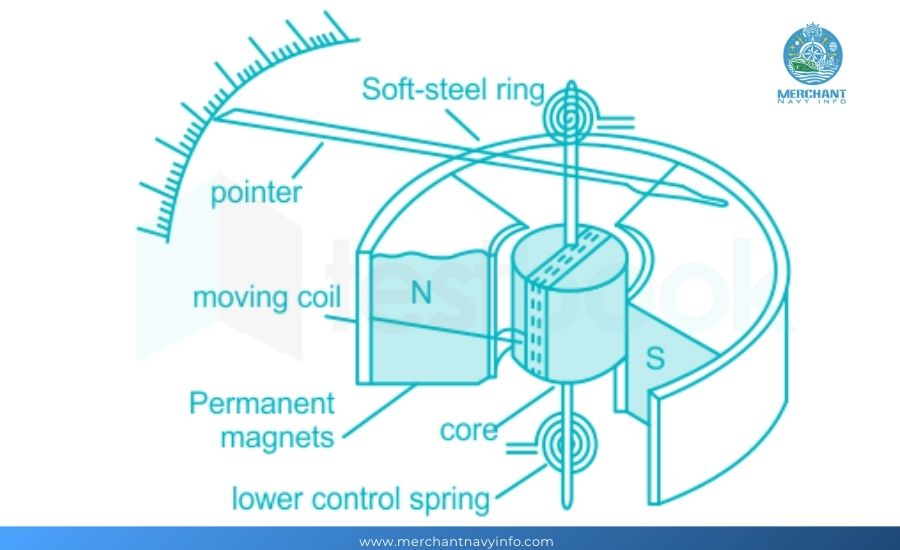
Permanent Magnet: PMMC devices use powerful permanent magnets to create a strong, uniform magnetic area. The magnet is usually in a horseshoe shape to provide a uniform space for the voice coil.
Voice Coil: A lightweight coil, usually made of thin copper wire, is wrapped around an aluminum body and placed between the poles of a permanent magnet. The coil is released to rotate about its axis.
Current: When current flows through the coil, it interacts with the magnetic field, creating pressure in the coil according to Fleming’s left-hand rule. The path of the pressure is perpendicular to the magnetic field and the path of the current.
Deflection: The pressure causes the coil to rotate. The amount of rotation is proportional to the current flowing through the coil. A pointer attached to the coil measures this deviation, moving on a calibrated scale to indicate the measurement.
Restoring Torque: A spring attached to the voice coil provides the restoring torque to ensure that the pointer returns to 0 when no current is flowing. The spring resists the current deviation, ensuring that the indicator correctly displays the current.
Magnetoelectric Principles
Magnetic Field: PMMC devices rely on a strong and uniform magnetic field provided by a permanent magnet, which is necessary for proper operation.
Lorentz Force: The first principle behind PMMC devices is the Lorentz force, which states that a current-carrying conductor in a magnetic field reports a voltage.
Components of a PMMC Full Model Tool
Permanent magnets are an essential component of a PMMC device, exposing the magnetic field required for its operation:
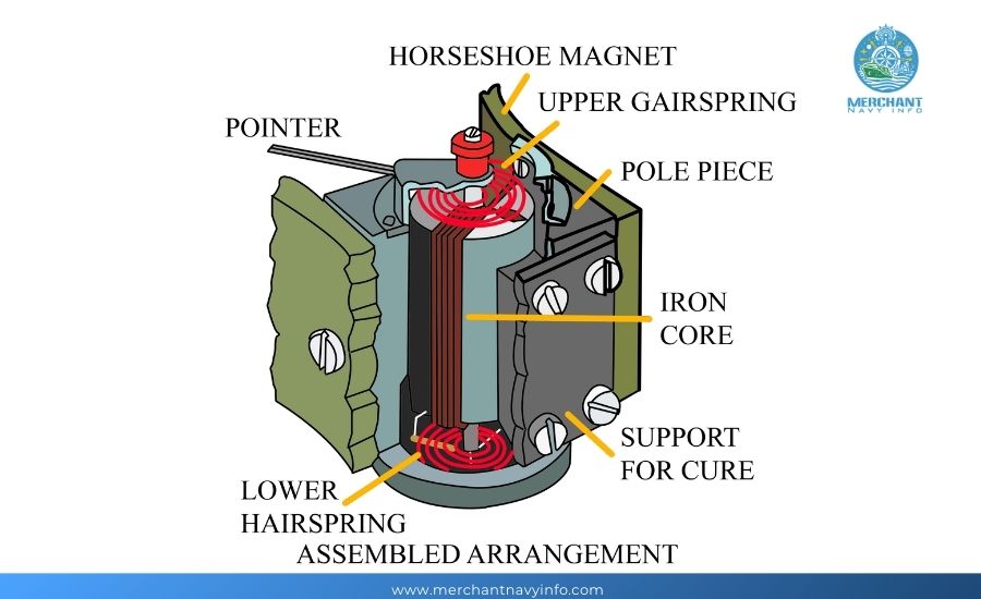
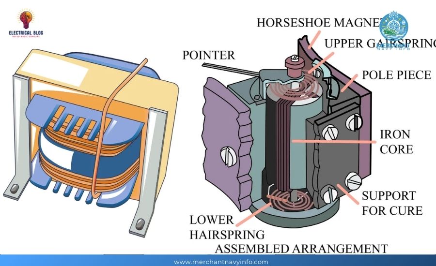
Construction: Permanent magnets are usually designed in a horseshoe or U-shape to produce a uniform magnetic field between their poles. This design ensures that the magnetic field is concentrated and stable in the area where the voice coil operates.
Material: Magnets are usually made of highly durable materials and magnetic strength, including Alnico (an alloy of aluminum, nickel, and cobalt) or rare earth magnets such as neodymium.
Magnetic field: The magnetic field produced by the permanent magnet interacts with the current flowing through the voice coil, generating the pressure required for deflection. The magnetic field must be strong and stable to ensure accurate measurements.
Essential Guide to Bow Thruster Construction and Functionality
Moving coil
The voice coil is the heart of a PMMC instrument, converting electrical current into mechanical motion. Its design and operation are critical to the device’s accuracy and sensitivity.
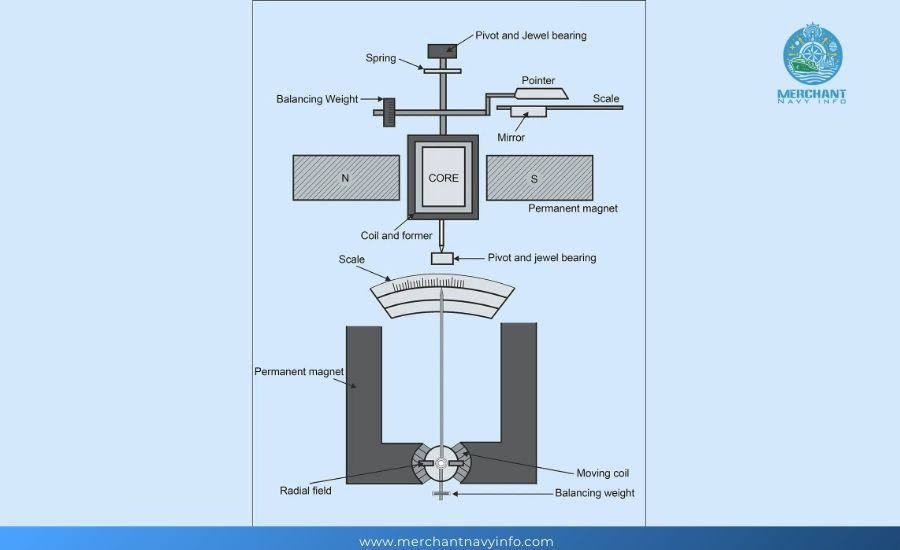
Construction: The voice coil is usually made of high-quality copper wire wrapped on a lightweight aluminum frame. The coil is suspended between the poles of the permanent magnet and can rotate freely about its axis.
Current: When fresh current passes through the coil, it removes pressure caused by its interaction with the magnetic field. This pressure causes the coil to move, and the degree of movement is proportional to the current.
Rotation and Deflection: The coil is mounted on jeweled bearings or tension rod suspensions to reduce friction and allow for smooth rotation. The angle and, therefore, index of the coil deflection is proportional to the current passing through the coil.
Types of All-Phase PMMC Devices
PMMC Analog Devices
PMMC devices are a traditional form of permanent magnet-moving coil devices, often used to measure electrical components visibly and continuously.
Construction & Design:
Permanent Magnets: Analog PMMC devices use permanent magnets to generate strong magnetic fields.
Moving Coil: A gentle coil of wire suspended between the poles of a magnet rotates in response to the current.
Pointer and Scale: The movement of the coil is transmitted to a pointer that moves on a calibrated scale, indicating the measurement.
Operation:
Real-Time Indicator: The indicator provides an instant visual indication of the measured quantity.
Linear Scale: Most analog PMMC devices have a linear scale, but some packages may require a logarithmic scale.
Sensitivity and Accuracy: These devices are known for their high sensitivity and accuracy due to minimal friction within the moving parts.
Applications:
Laboratory Measurements: Often used in laboratories for unique voltage, current, and resistance measurements.
Panel Meters: These meters are used above panels and dashboards for real-time tracking of electrical parameters.
Educational Tools: Widely used in academic settings to train on basic electromagnetics and electrical measurement standards.
PMMC Digital Devices
PMMC devices are a modern version of traditional PMMC designs incorporating virtual technology to increase capacity and availability.
Construction & Design:
Permanent Magnets and Moving Coils: Similar to analog PMMC devices but with additional virtual components.
Digital Displays: Replace traditional pointers and meters with virtual readouts, including LCD or LED displays.
Operation:
Digital Conversion: The analog signal generated by the moving coil is converted to a virtual signal using an analog-to-digital converter (ADC).
Display & Processing: The virtual signal is processed and displayed on a virtual screen, providing clear and unique measurements.
Benefits of Full-Form PMMC Devices
High Accuracy
Measurement Accuracy:
PMMC devices are known for their high accuracy in measuring electrical components such as current and voltage. Precision comes from the precisely wound-moving coil and the strong magnetic field provided by the permanent magnet.
Small Errors:
PMMC devices are designed to minimize errors caused by friction and mechanical imperfections. The jewel bearings or tension rod suspension inside the moving coil mechanism ensures clean and crisp motion.
Consistent Readings:
The permanent magnet’s magnetic field balance ensures that the measurement remains stable over time, contributing to the device’s high accuracy.
Linearity and Stability
Linear Scale:
PMMC devices typically operate on a linear scale, meaning that the pointer deflection is proportional to the current flowing through the coil. This linearity makes it easier to study and interpret the measurements accurately.
Stable Magnetic Field:
The use of bright permanent magnets ensures a strong magnetic field, which is critical to the device’s continued performance. This balance allows the device to maintain its calibration and accuracy over time.
Reliable Performance:
The mechanical and electrical components of PMMC devices are designed to provide reliable, repeatable performance. The rugged output ensures the device can withstand normal use without significantly reducing accuracy.
Other Benefits
Allergies:
PMMC devices are very sensitive and can detect and measure small changes in electrical components. This sensitivity is due to the finely wound transmission coils and the low inertia of the transmission components.
Wide range of applications:
These devices are very flexible and can be used in many applications, from laboratory measurements to commercial monitoring. With appropriate adjustments, they are suitable for both AC and DC measurements.
Disadvantages of PMMC Full Model Tool
Sensitivity to External Magnetic Fields
Magnetic Interference:
PMMC devices are very sensitive to external magnetic fields. These fields can distort the device readings by interacting with the permanent magnetic field, resulting in erroneous measurements.
Shielding Requirements:
PMMC devices often require magnetic shielding to reduce the effects of external magnetic fields. This adds cost and complexity to the device, and even with shielding, some residual interference can affect accuracy.
Environmental Sensitivity:
The ergonomics of PMMC devices may reduce their accuracy and overall performance. Magnetic fields from nearby appliances or other sources may also cause measurement errors.
Limited to DC Measurements
Cannot Directly Measure AC:
PMMC devices are inherently designed for direct direct current (DC) measurements. They cannot directly measure alternating current (AC) because the average deviation of AC over a cycle is zero due to the constant bypass path for the current.
Corrective Requirements:
To measure AC with a PMMC device, the AC signal must be rectified to convert it to DC. This includes additional add-on components, such as rectifiers or diode bridges, which can introduce errors and reduce the overall accuracy of the measurement.
Complexity of AC measurement:
The need for rectification adds complexity to the device design, making the PMMC device larger and more complex to use for AC measurements. It also increases the cost capacity and failure factors within the device.