A ship’s hull is the ship’s most notable structural unit. The hull of a ship is the watertight shell of a ship that protects the ship’s cargo. Machinery, and storage space from elements such as flooding and structural damage. However, this is not enough to understand all aspects of the hull.
This article explains how hull of a ship is designed, taking into account various factors considered throughout the life of the ship. It also discusses how the hull of a ship design is the most important part of the overall ship design and shipbuilding project. We’ll see if it plays an important role.
Hull-44elated Nomenclature
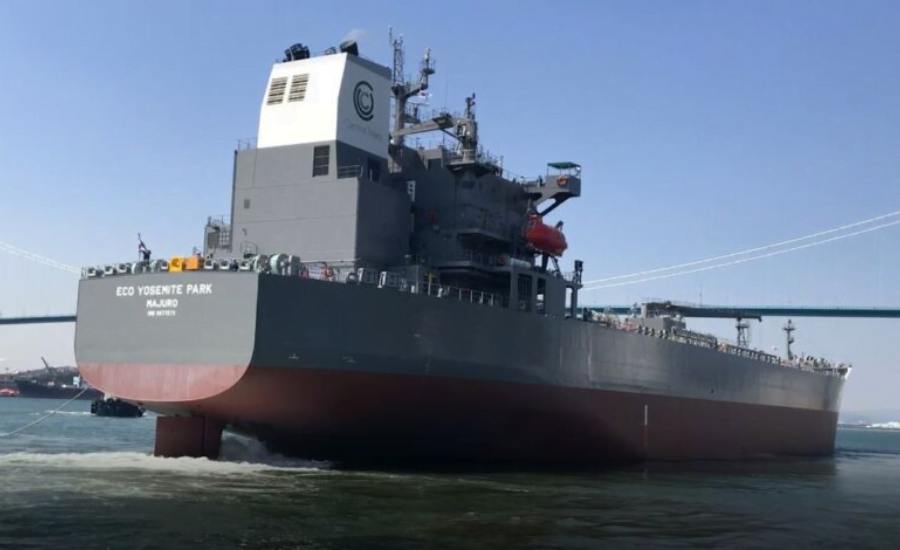
The general outline of a conventional hull. Understanding the meaning and application of relevant nomenclature is fundamental to understanding ship design and shipbuilding technology.
Bow and Stern
The forward contour of the hull of a ship is called the bow. And also the rearmost contour is called the stern. The shaft is the front part of the bow.
Forward Perpendicular
If a perpendicular is drawn at the point where the bow intersects the waterline. This imaginary perpendicular is called the forward perpendicular. Most hydrostatic calculations use the forward perpendicular as the hull forward reference.
Immediate Lead
Depending on the designer, the Immediate Lead is a plumb line that passes through the after side of the rudder post or through the center line of the rudder pin. The back perpendicular is the backreference line for all hydrostatic pressure calculations.
Length Between Perpendicular Lines
The length between the front and rear perpendicular lines is the length between the perpendicular lines. LBP is a very important parameter in all stability calculations, so calculating his LBP at various drafts. Is an important step when performing a stability analysis.
Steep Slope
The upward curve formed by the main deck relative to the height of the midship deck is also called a steep slope. It is typically used to channel green water from the fore and also aft end to midship and drain into the bilge. To protect the forward anchor machinery from waves, the forward shear is usually greater than the aft shear.
Summer Loading Line
The vessel’s waterline in seawater is when the vessel is at design weight and ballast. This is also called a draft draft. This serves as the reference for all other loading lines on the ship.
Waterline Length
The length of the hull of a ship at the summer loading line is the length of the ship’s waterline. This length plays an important role in ship hydrostatic pressure calculations and propeller design calculations.
Overall Length
The length between the front and rear of the hull is the total length. This length plays an important role when designing the ship’s berthing plan. For shipyards with multiple construction docks, the ship’s length, width, and depth are important factors when selecting the appropriate building block for the ship.
Hull Lines and Shapes
The first step in designing a hull of a ship is to design its shape and form. The hull shape is estimated using various shape factors and is described as follows:
Block Coefficient
The interception factor is the ratio of the underwater volume of the ship to the volume of an imaginary rectangle surrounding the underwater part of the ship. The length, width, and height of this enclosing rectangle correspond to the length between the ship’s perpendicular, maximum width, and draft, so the blocking factor is expressed as
The block coefficient value is expressed as A ship with a rectangular cross-section. Therefore, for a typical ship hull shape, it is less than 1. The higher the blocking factor, the more bulging the hull shape (oil tankers, bulk carriers, etc.). The finer the hull shape, the lower the blocking factor (container ships, warships, etc.).
Midship Factor
The midship Factor is the ratio of the submerged area of the midship section to the surrounding rectangle. Therefore, it is expressed as follows: There are a number of other shape factors, such as the prismatic factor and the volume factor, which are essential parameters used to define the volume distribution along the length of the hull. Once these coefficients are determined from statistical studies, the hull lines are created. The hull line plan consists of three views. To understand line plans, we first need to know what butt lines and water lines are. If a ship’s hull is cut into several pieces lengthwise. H. If the hull is cut every 2 meters from port to starboard, longitudinal sections are created every 2 meters. The outline of each longitudinal section is called the butt line, and this is exactly what is shown on the profile plan, as shown below.
The reference lines for a profile view are the station (the vertical grid line showing the longitudinal position) and the waterline (the horizontal line showing the longitudinal position). If the hull is cut along each waterline, each waterline will have a distinct curve. Since the hull is symmetrical about the centerline, it is common to draw curves on either side of the centerline. This view is called the ship’s hull plan or half-beam plan. Cutting the hull into sections at each station yields the following hull plan. A common practice when drawing a plan view of a ship’s hull is to specify all half sections (due to the symmetry of the ship). Sections forward of the centerline are drawn to the right of the centerline, and all sections from the centerline to the stern are drawn to the left.
Hull Structure and Strength
Hull structural design accounts for approximately 70 percent of the entire ship’s structural design. The steps to design a hull structure are as follows:
Step 1: Calculate the Loads on the Hull
This is where classification society rules come into play. The regulations contain special formulas for calculating wave loads on the hull. Bending moments in still water, bending moments in waves, and shear forces must be calculated using these formulas. These load values serve as target values throughout the design process.
Step 2: Midship Sizing Calculations
The dimensions of all structural elements of the ship (plates, stiffeners, beams, beams, columns, etc.) are collectively referred to as sizing. The loads calculated in step 1 are used to determine dimensions, and dimensions are calculated for each frame structural member.
Step 3: Module of Midship Section
A structural drawing of the midship section is created according to the calculated dimensions. The midship neutral axis is then determined, and the midship section modulus is calculated. At this point, two criteria must be met:
- The obtained midship cross-sectional area shall be equal to or greater than the minimum drag coefficient value determined by the empirical formula of the regulations.
- Calculate the bending stresses in the deck and keel and check if the stress values are within the required safety factor.
In the illustration of the midship section above, the blue line (NA) is the neutral axis of the section. The bending stress diagram is drawn with the neutral axis as the reference (origin), as shown in the stress diagram below, and the upper and lower parts of the diagram show the stress values at the deck and keel, respectively.
Why do you think it is important to design the structure of the nave section of a ship before all other parts? After reading this article, you will understand why the center of the ship is the most important structural part of the ship. Understand why this is an important area.
Step 4: Dimension Calculation for Each Frame
Once the midship dimensions meet the criteria, the dimensions of the structural elements of each frame are calculated, and the corresponding frame-related structural drawings are created. Special formulas are applied to the front, rear, and bulkheads to create the drawings.
Step 5: Calculate the Steel Weight
The obtained dimensions are used to calculate the steel weight of the ship. This is where the iteration begins. If the calculated steel weight exceeds the empirically and statistically determined value, the designer will use lighter steel in appropriate areas to keep the weight of the lighter ship within limits. You may need to consider this or make other decisions.
Step 6: 3D Structural Model Development and FEA analysis
Use the structural drawings of each frame to create his 3D structural model of the entire airframe. This process is the most time-consuming, as the accuracy of this model directly affects the results of the subsequent finite element analysis. Perform 3D meshing on 3D models and perform finite element analysis under various conditions. Based on the results of these analyses, classification societies are now approving the ship’s structural design, as it provides more reliable data than linear calculations.
Hull Heading Stability
Another important aspect of a ship’s hull is its directional or heading stability at sea. In other words, its maneuverability. To assess the bare hull maneuverability, the following aspects are evaluated:
Straight Line Stability
When a ship traveling in a straight line changes direction due to a disturbance but continues to travel straight in the new direction without the aid of the rudder, the ship is said to have straight-line stability.
Directional Stability
A ship moving in a straight line is said to have directional stability when it experiences a disturbance and continues along a new path parallel to its original direction. Although directional stability is not possible without the aid of control surfaces (such as rudders), straight-line stability makes it easier to achieve directional stability.
Route Stability
If a ship moving in a straight line is disturbed by an external source and continues on the same route (after some fluctuations), it is called route stability. Trajectory stability, like directional stability, can only be achieved if straight-line stability is achieved.