As a seafarer on a vendor transport or as a dispatch manager/owner of a vessel. One of the greatest bad dreams is that of any kind of oil contamination mishap on a dispatch. A transport produces oil and water blend on a day-by-day premise which should be isolated from each other. Sometime recently releasing the grimy water out of the transport utilising hardware such as an oily water separator.
MARPOL incorporates a direction beneath. Add I, which limits the oil substance within the bilge water that a vessel can authentically release into the ocean. It is now a necessity for all vessels to have an oil release checking and control framework. In conjunction with oil sifting gear known as the Oily Water Separator (OWS).
Control for Oily Water Separator
As per Add 1 of MARPOL beneath control 4 indicated beneath passages 2, 3, and 6. Any coordinated release of oil or Oily water blend into the ocean should be denied. The direction assist clarifies how an Oily water blend can be treated on board and can be released out at the ocean:
Oil Water Release Control
For a transport with 400 GT and over, the release of the oil blend can be done beneath the following conditions:
- The transport is on course
- The Oily blend is prepared through an oil-water separator channel assembly, the prerequisites of control 14 of this Annex;
- After passing the oil-water separator framework, the oil substance of the profluent, without weakening, does not surpass 15 parts per million;
- The oily blend does not begin from cargo pump-room bilges on oil tankers
- In an oil tanker dispatch, the oil-water blend isn’t blended with oil cargo buildups
When the ship is utilised within the Antarctic zone, any release into the ocean of oil or Oily blends from any vessel should be denied.
Important Oily Water Separator (OWS) Necessity
- As per the MEPC 107(49), the bilge alert or an Oil Substance Screen (O.C.M.), which gives for the inside recording of caution conditions, must be certified by an authorized organization
- 2 The O.C.M. given with the Oily water separator must be tamper-proof
- The O.C.M. must enact and sound an alert at whatever point freshwater is utilized for cleaning or focusing purposes
- Separator able to accomplish 15 ppm on sort C emulsion.
- The oily water separator must pass through the least release restraint of 15 ppm.
- Sensors and cautions must be introduced on the gear where it can’t be checked and kept up all the time.
The OWS must only be worked by officers who are recognizable with the gear and who are straightforwardly directed by the Chief Design, who bears sole responsibility for its support and operation. When the hardware isn’t in use, the Chief Engineer is responsible for guaranteeing that a strategy is in put to bolt it out to anticipate unauthorised operation with keys in ownership of the Chief Build.
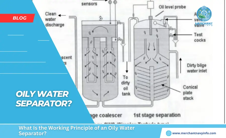
Development and Working of Oily Water Separator (OWS)
OWS comprises of primarily three fragments
1. Separator unit
This unit comprises capture plates, which are interior, a coarse isolating compartment, and an oil collecting chamber.Here, the oil features a thickness which is lower than that of the water, which makes the previous rise into the oil collecting compartment, and the rest of the non-flowing oil blend settles down into an fine settling compartment after passing between the capture plates.After a period of time, more oil will isolated and collected within the oil collecting chamber. The oil substance of water that passes through this unit is around 100 parts per million oil.
A control valve (pneumatic or electronic) discharges the isolated oil into the assigned OWS sludge tank.The radiator may be joined into this unit for a smooth stream and partition of oil and water.A heater may be consolidated in this unit either in the middle or now and then within the foot portion of the unit (depending upon the region of operation and capacity of the separator hardware) for smooth stream and separation of oil and water. The primary stage makes a difference in expelling a few physical pollutions to realize fine filtration within the afterward stage.
2. The Channel unit
Usually, a partitioned unit whose input comes from the release of the, to begin-with the unit.This unit comprises of three stages – channel arrange, coalescer organize and collecting chamber.The debasements and particles are isolated by the channel and are settled at the foot for evacuation.Within the moment organized, the coalescer actuates a coalescence handle in which oil droplets are joined to increase their estimate by breaking down the surface tension between oil beads within the blend.These large oil particles rise above the blend within the collecting chamber and are evacuated when required.
The yield from this unit should be less than 15 ppm to satisfy legitimate discharge criteria.If the oil content in an water is more than 15 ppm, upkeep work such as channel cleaning or reestablishment of filters is to be done as required.A freshwater channel association is additionally provided to the channel unit to clean and flush the filter. This can be more often than not done some time recently and after the operation of an oil separator unit.
3. Oil Substance Monitor and Control Unit
This unit’s capacities are divided into two parts: monitoring and controlling.The ppm of oil is ceaselessly checked by Oil Substance Screen (O.C.M.); in case the ppm is tall, it’ll deliver an caution and bolster information to the control unit.The control unit persistently screens the yield flag of O.C.M., and on the off chance that a caution emerges, it will not permit the Oily water to go over the edge by working a 3-way solenoid valve.There, as a rule, are three solenoid valves commanded by the control unit. These are found within the to begin with unit oil collecting chamber, second unit oil collecting chamber and one on the release side of the oily water separator, which could be a 3-way valve.
The 3-way valve channel is from the OWS release, where one outlet is over the edge and the second outlet is to the OWS slime tank.When O.C.M. gives an alarm, the 3-way valve releases the Oily blend within the sludge tank. A little pipe association of new water can be provided to the O.C.M. unit for flushing. At whatever point this line is in utilize, an caution is sounded and recorded in the O.C.M. log, guaranteeing a record to check the release valve was closed amid this period.
Components Influencing Partition of Oil From Bilge Water
A few components influence the division of oil from bilge water, such as :
Thickness
As water has more thickness than oil, it tends to rise.
Satisfactory Thickness Contrast
Seawater has more thickness than freshwater. In this way, by utilizing seawater, it is ready to increase the rate of division.
The viscosity of Continues Fluid
we know a less thick liquid with less viscosity offers way better conditions for oil to move toward the surface than a dense fluid with more consistency. Here, the consistency of new water is less than that of seawater.
Temperature
Temperature plays a vital part. It may be a significant figure that influences both thickness and consistency. When the temperature is low, among liquid particles limiting division, thickness is higher.
Estimate of particles
The partition of oil from water is specifically relative to the size of oil particles.
Disassembling Strategy for cleaning oil water separator
- To begin with, stop the O.W.S. Bilge pump
- Best the steam stream to heating coils
- Closed the fundamental over-the-edge valve
- Open vent for both partition and filtration chamber
- Gradually open the deplete valve of each segment at the foot
- Oil must be depleted out
- All electric and pipe associations must be evacuated
- Nuts and jolts of the beat cover of the division chamber must be opened.
- Confuse plates should be taken out and cleaned with a brush and oil. Presently open all the nuts and jolts of the beat cover of the division chambers.
- The condition of the coalescer channels must be inspected.
- If fundamental, put back a modern channel.
- After everything is over, amass the whole system and fill the O.W.S.O.W.S. with new, clean water to check for any leakage.
What Causes an Oily Water Separator to Break Down?
The oil-to-water gravity angle is the premise upon which the Oily Water Separator works. Due to an general difference in weight between an oil molecule and a molecule of water of similar volume, the force exerted on an oil globule to travel in water corresponds to the distinction in weight.
A globule’s resistance to portability is determined by its measure and the consistency of the liquids in which it is contained.
In this way, a tall rate of partition is regularly favoured by
- the expansive estimate of the globule.
- Higher framework temperature (which influences both the particular gravity contrast of the oil and water and the viscosity of the water) and the usage of salt water.
2. Pumping Thought
A vital consideration is to minimize any deterioration of large-sized oil beads within the nourishing oil for a separator, which may be incredibly affected by the type and rating of the pump utilized within the process.
Numerous bilge pumps are centrifugal, and they are often utilized as supply pumps for the separator.
A positive relocation pump, such as a slow-running twofold vane, screw, responding, or gear pump, allows the separator to work significantly superior since it does not create a significant number of minor beads. Pumping after the separator may result in a release with a concentration of less than 15 ppm without the requirement for 2nd Arrange channels.
As a result of the going before two contentions, it is clear that even if the separator is legitimately maintained and worked, the taking after causes might result in the separator failing:
- When the separator has an unusually tall throughput.
- Breakdown of divider globules due to extraordinary rolling and pitching of the dispatch
- The pump type and rating aren’t coordinating, causing too much turbulence
- Due to the high pumping rate, there’s turbulence.
Maintenance of Oily Water Separator
To stay in fabulous operating condition, an oily water separator must be properly and routinely kept up. When these gadgets are not drained and cleaned consistently, oils and other flotsam and jetsam clog them and render them in inoperable. This may result in oil levels in the released water exceeding the emanating limitations mentioned.
Oily water separator models that is an elevated above the ground are significantly easier to clean since everything is easily accessible. This is since there are no confined places, and plates may be cleaned, removed, and changed. All forms of above-ground structures may be kept up from the ground. Moreover, strong waste may be helpfully cleared by means of a enormous gap at ground level.
When utilizing a below-ground oil-water separator, it is basic to follow to a tight maintenance plan. It is more likely that you just will neglect cleaning the unit since it is buried within the ground. These are the oil-water separator support strategies to take after.
After a Month of Utilisation, Do the taking After Checks and Cleanings on the Inlet Area
- Turn off the unit’s supply of water.
- Open the cover of the unit.
- If there’s any oil present, evacuate it and arrange it in agreement with corporate and legal regulations.
- Water should be depleted from the separator.
- Take a measurement of the depth of the leftover solids and record it. Within the future, this will serve as a foundation for arranging maintenance and cleaning assignments.
- Get rid of the solids on the off chance that is required.
The media plates will have to be be cleaned once all of this has been completed. They may be cleaned either interior or exterior the unit. Embed a low-pressure hose in between the plate crevices on the plate packs to clean them without destroying them. Remove any debris drained from the plates by draining it down the hopper outlet.