Several electromechanical and electrical panels are installed on board the ship. To ensure safe and efficient movement from one port to another. Electrical machines and systems must be regularly maintained and inspected to avoid breakdowns during operation. To analyze these machines and keep them in proper working condition. Various instruments are used on board ships that measure various electrical parameters. The Permanent Magnet Moving Coil (PMMC) is one such piece of equipment. Commonly used onboard ships and used for multiple applications. Other common name for this equipment is a galvanometer and a galvanometer.
PMMC Instrument Working Principle
Moving Coil with Permanent Magnet
Principle of Operation When a current-carrying conductor is placed in a magnetic field. The conductor experiences a force and tends to move in the direction of Fleming’s left-hand rule.
Fleming’s left-hand rule
When the index finger, middle finger, and thumb of the left hand are gripped at right angles to each other. The thumb directs the direction of force toward the conductor, also pointing to the index finger. The finger indicates the direction of the magnetic field. And also the middle finger indicates the direction of the current in the wire.
Related Equations
The interaction between the induced magnetic field and the magnet field produced by the permanent magnet. Produces a deflection torque that causes rotation.
Three Important Torques For This Equipment Are
Deflection torque
According to Fleming’s left-hand rule. The force F perpendicular to the direction of current flow and also the direction of the magnetic field can be expressed as:
F = NBIL, where N: Number of turns of wire on the coil
B: Magnetic flux density in the air gap
I: Current in the moving coil
L: Vertical length of the coil
Theoretically, The torque (here electromagnetic torque) is equal to the product of the force. And also the distance to the point of suspension.
Therefore, the torque on the left side of the cylinder is TL = NBIL x W/2. And also the torque on the right side of the cylinder is TR = NBIL x W/2. Therefore, the total torque = TL + TR T = NBILW or NBIA, where, A is the effective area (A = L x B)
Controlling Torque
This torque is generated by the action of a spring, counteracting the deflection torque and allowing the pointer to come to rest at these points. The two torques are equal (electromagnetic torque = control spring torque). The value of control torque that depends on the mechanical design of the coil spring or band suspension.
The control torque is directly proportional to the deflection angle of the coil.
Control torque Ct =Cθ where θ = deflection of angle in radians, C = spring constant Nm/rad.
Damping Torque
This torque ensures that the pointer reaches the equilibrium position, i.e., H. Fits on the scale without shaking, allowing for accurate readings. In PMMC, when the coil moves in a magnetic field, eddy currents are generated in the metal body or core around which the coil is wound or at the circuit of the coil itself, which impedes the movement of the coil, causing the pointer to vibrate slowly, and then almost Stops immediately without vibration.
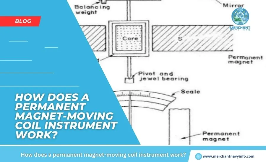
Construction of PMMC
A coil of thin wire is attached to an aluminum frame (spindle) that is placed between the poles of a U-shaped permanent magnet made of a magnetic alloy such as Alnico.
The coil is rotatably mounted on a jewel bearing, allowing it to rotate freely. Current is supplied to the coil through two spiral springs. The coil carrying the current to be measured moves in a strong magnetic field created by a permanent magnet, and a pointer is an attached to the spindle to indicate the measured value.
How PMMC works
When a current flows through the coil, a magnetic field proportional to the current is generated in the ammeter. Deflection torque is generated by the electromagnetic effects of the current and magnetic field in the coil.
When the torques are a balanced, the moving coil stops, and its angular deflection represents the current measured with respect to a fixed reference called a scale. If the permanent magnetic field is uniform and the spring is linear, the deflection of the pointer will also be linear.
Control torque is provided by two flat phosphor bronze coil springs. These springs act as flexible connections to the coil conductors. Damping is caused by eddy currents generated within the aluminium coil, which prevents the coil from oscillating.
Applications
The PMMC has a wide range of applications onboard ships. For example, you can use:
Ammeter
When using the PMMC as an ammeter, the moving coil is connected through a suitable low resistance shunt, except in the lowest current range, so that only a small portion of the current flush. The main current flows through the coil.
The shunt consists of multiple thin plates of alloyed metal, usually magnetic and with a low-temperature coefficient of resistance, fixed between two solid copper blocks. A resistor made of the same alloy is also connected in series with the coil to reduce errors due to temperature fluctuations.
Voltmeter
When using the PMMC as a voltmeter, the coil is connected in series with a high resistance. The rest of the functionality is the same as above. The same moving coil will can be used as an ammeter or voltmeter to replace the above configuration.
Galvanometer
Galvanometer is used to measure small current values and their direction and strength. It is primarily used onboard to detect and compare different circuits within a system.
Ohmmeter
An ohmmeter is used to measure the resistance of a circuit by applying a voltage across a resistor using a battery. In a galvanometer, the flow of current is determined by the resistance. The scale of a galvanometer is in ohms, and as the resistance changes with a fixed voltage, the current flowing through the meter also changes.
PMMC Advantages
- PMMC has low power consumption and high accuracy.
- It has an evenly divided scale and can cover an arc of 270 degrees.
- PMMC has a high torque-to-weight ratio.
- It can be converted to an ammeter or voltmeter with an appropriate resistance value.
- Has efficient damping characteristics and is not an affected by stray magnetic fields.
- There are no losses due to hysteresis.
Disadvantages of PMMC
- Moving coil devices can only be used with his DC power supply as the reversal of current creates torque in the coil.
- Because it is very sensitive, an alternating current circuit with a rectifier may be used.
- Expensive compared to iron-moving coil equipment.
- An error may be displayed due to a decrease in the magnetism of the permanent magnet.
What are the causes of errors in PMMC?
Temperature Effects
PMMC reading errors can result in temperature changes that affect the resistance of the moving coil. The temperature coefficient of the copper wire in the moving coil is 0.04 per degree Celsius temperature increase. Because the coil has a low-temperature coefficient, it heats up faster, increasing resistance and causing errors.
Spring Material and Age
Another factor that can cause errors in PMMC readings is the quality and deformation of the spring. If the spring deteriorates, the pointer will no longer be able to display the correct value, and an error will occur.
Deterioration of magnets over time
As deterioration progresses over time, the magnetic effect of permanent magnets decreases due to heat and vibration, causing measurement errors.
Can the PMMC be used to measure alternating current?
If the frequency is low enough, the PMMC can measure AC current using a rectifier that converts the measured quantity to a DC current, typically less than one mA. Adding the appropriate scale completes the measuring device.
What happens when used with high-frequency alternating current?
If the frequency of the AC current is high, the meter will oscillate around the zero value (preferably checked with a zero point meter) and eventually stop responding to the AC current.
What are permanent magnets made of?
Permanent magnets are made up of special alloys, such as:
- Aluminum-Nickel-Cobalt (Alnico)
- Strontium-Iron
- Neodymium-Iron – Boron
- Samarium – Cobalt.